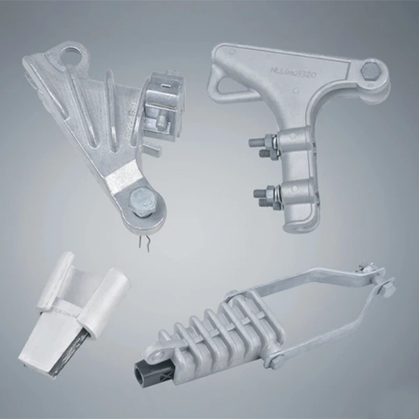
| CDG Release Wire Fixing Clip is suitable for securing overhead conductors and insulators of 10kV and below. | 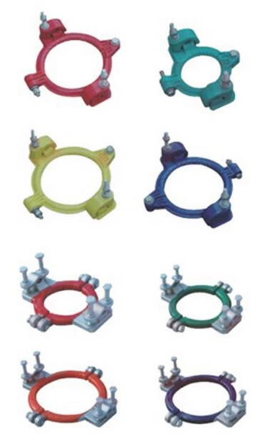 |
| Advantages 1. Made of high-strength aluminum alloy and high-strength engineering plastics; 2. Easy installation, attractive appearance, and durable; 3. Low power loss and maintenance-free; 4. Safe and reliable line operation; 5. Features a deadweight release function. |
|
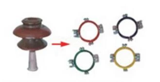
Naming 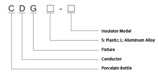 |
Specifications and technical parameters
| Model | Applicable Voltage (kV) | Applicable Conductor Cross-Section (mm²) | Main Dimensions (mm) | Remarks | ||
| A | B | C | ||||
| CDGS-P20 | 10kV and below | 25~240mm² | Ф106 | 200 | 180 | Casing: Weather-Resistant Plastic |
| CDGS-P15 | Ф84 | 160 | 130 | |||
| CDGS-PS15 | Ф66 | 153 | 120 | |||
| CDGL-P20 | 10kV and below | 25~240mm² | Ф106 | 178 | 157 | Casing: Aluminum Alloy |
| CDGL-P15 | Ф84 | 160 | 135 | |||
| CDGL-PS15 | Ф66 | 146 | 117 | |||
| CDGL-PSN | 20kV | 25~240mm² | Ф76 | 170 | 150 | Insulator: PSN-170/12.5S |
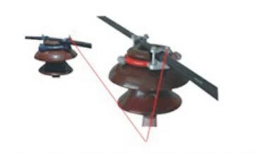
Correct installation method and effect diagram
 |
 |
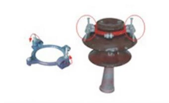 |
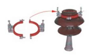
| 1. Select the appropriate retaining clamp according to the insulator model. | 2. Unbolt the retaining ring and insert it onto the top neck of the insulator. Tighten the bolts while aligning the wire trough with the conductor. | 3. Loosen the bolts on the conductor clamps at both ends (for plastic retaining clamps, loosen the bolts to rotate the conductor). |
 |
 |
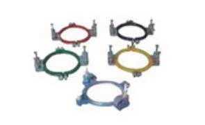 |
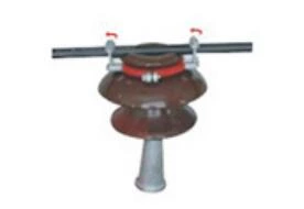
| 4. Place the conductor into the trough above the porcelain bottle, attach the retaining plate, and hand-tighten the conductor clamp bolts. | 5. Use a wrench to evenly tighten the retaining plate bolts to the appropriate level. Installation is complete. | 6. The conductor clamp not only has a release function, but also has four colors (red, yellow, blue, and green) that correspond to the phase of the conductor. |


