Applications
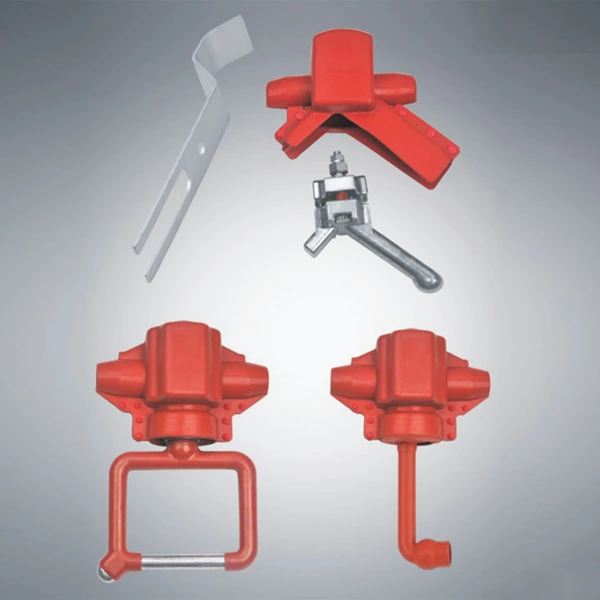
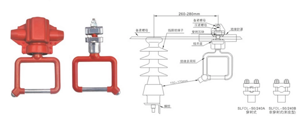
The SLFDL lightning protection and detection grounding ring is a novel two-in-one product installed on the load side of line insulators. It is specifically designed to prevent lightning breakage of 10-20kV overhead insulated conductors and to serve as a voltage detection and grounding device during maintenance and construction. Currently, insulated conductors are commonly used in distribution network overhead lines of 10-20kV and below. However, the inherent lightning resistance of these insulated lines is a significant problem. Detection grounding rings, fault indicators, arc clamps, branch clamps, and other equipment are often hung in series on the poles, creating a cluttered and unsightly line. This product is easy to install, combining two components into one, simplifying lines and reducing costs, providing a more cost-effective solution for power companies. Available models include the SLFDL-50/240B, a non-piercing type, and the SLFDL-50/240A, depending on user needs.
Model Specifications and Performance Parameters
| Model Specifications | Rated Voltage (kV) | Insulated Conductor Cross-Section mm² | Lightning Full-Wave Impulse Withstand Voltage (Peak Value) kV | 1-Minute Power Frequency Withstand Voltage (RMS) kV | Power Frequency Arc Current (RMS) kA | Remarks | |
| Dry | Wet | ||||||
| SLFDL-50/240A | 12 | 50/240 | 75 | 42 | 30 | 12.5 | Piercing Type |
| SLFDL-50/240B | 12 | 50/240 | 75 | 42 | 30 | 12.5 | Non-Piercing Type |
Model Specifications
Structural Features
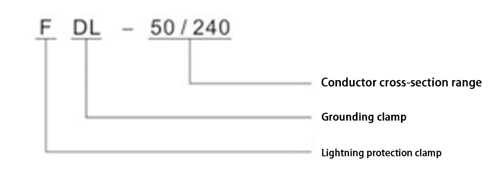
1. It consists primarily of an insulating shield, a compression nut, a clamping block, a wire clamp seat, and an insulating multi-purpose ring.
2. The insulating shield is made of an organic composite material, offering excellent insulation, aging resistance, and flame retardancy.
3. The multi-purpose ring combines the arc starter and the test grounding ring into one component. When a lightning strike occurs, discharge occurs between the arc starter and the insulator metal parts, causing the follow-flowing power-frequency arc to transfer to the arc starter and burn, thereby protecting the insulated conductor from damage. It can be used for electrical testing and temporary grounding during maintenance and repair work.
4. This product features multiple switching paths, is easy to install, and offers reliable performance, significantly reducing operator workload.
5. It can withstand approximately five high-current power-frequency arc burns.
Discharge gap installation dimension table
| Mounting Post Model | Discharge Gap (mm) |
| P-10 Insulator | 125~135 |
| P-15 Insulator | 140~150 |
| P-20 Insulator | 150~170 |
| PS-15 Insulator | 150~170 |
| PS-20 Insulator | 170~180 |
| S-210 Porcelain Crossarm Insulator | 270~300 |
Installation method
1. This product is installed on the load side of the line insulator (such as PS-15 high-voltage line column insulator). For the stripping type, peel off the insulation layer about 70mm according to Figure 1, and fasten the lightning protection and electrical grounding ring to the conductor; there are two ways to fasten the piercing type wire clamp: (1) Torque nut fastening method: insert the insulated wire into the wire clamp slot as parallel as possible, first tighten the torque nut by hand, and then use a socket wrench to tighten it evenly until the torque nut head falls off. (2) Set the torque value of the torque wrench according to the wire cross-sectional area and weather temperature; 26-35Nm, use a torque wrench to tighten the two pressure nuts alternately and symmetrically, and check with the naked eye that the insulation layer of the wire is close to the wire clamp arc groove. The root of the thorn teeth cannot be seen. Then tighten the backup nut to prevent the pressure nut from loosening;
2. During installation, adjust the distance between this product and the line insulator according to Figure 1 and the discharge gap installation dimension table;
3. The insulation cover is installed on the outside of the wire clamp seat and fixed with a fixing buckle. (Please refer to the product installation manual for details.)
Notes
1. Before and after thunderstorms, inspect the line to ensure the product is in proper installation condition and to check for damage. Adjust or replace if necessary.
2. If a relay protection device with automatic reclosing is installed at the line start, properly adjusting the parameters can effectively reduce the number of line outages.
Piercing Type Outer Gap Arrester
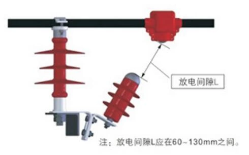 |
Principle and Features The piercing external gap arrester is suitable for 10kV overhead insulated distribution conductors. It utilizes a patented piercing arc striker structure that penetrates the conductor insulation to establish an electrical connection. The lower end of the arc striker faces the arc striker at the top of the arrester, forming a series external discharge gap with a spacing of 60 to 130 mm. This distance is adjusted by the relative movement of two mounting plates at the bottom of the arrester. Under normal conditions, the high-resistance arrester resistor and discharge gap remain inactive. Only when a lightning overvoltage exceeding the specified threshold occurs will the discharge gap break down, forming a short-circuit path. The subsequent power-frequency arc then burns across the external gap, releasing the overvoltage energy and protecting the conductor from burns. After the voltage is released, the arrester resistor resumes its high-resistance gap and discharge ceases. |
Technical parameters and selection table of puncture type external gap arrester
| Product Model | System Nominal Voltage kV | Arrester Rated Voltage kV | DC Reference Voltage kV | Power Frequency Withstand Voltage kV | Lightning Impulse 50% Discharge Voltage kV | Wire Clamping Range (mm) | Applicable Wire Specifications | Conductor Diameter (mm) | Insulation Outer Diameter (mm) | Applicable Torque (N*m) |
| FHY5C-10C-1 | 10 | 13 | ≥20 | ≥80 | ≤160 | Ф16~22 | JKLY-50~120 | 8.5~13 | 16.1~21 | 23 |
| JKLGY-35/6-95/20 | 7.75~13.18 | 16.6~22 | ||||||||
| FHY5C-10C-2 | 10 | 13 | ≥20 | ≥80 | ≤160 | Ф22~28 | JKLY- 120~240 | 14.6~18.4 | 22.6~26.4 | 26 |
| JKLGY-120/7~185/45 | 13.718~18.62 | 22.6~27.4 | ||||||||
| FHY5C-10C-3 | 10 | 13 | ≥20 | ≥80 | ≤160 | Ф26~30 | JKLY-300 | 20.6 | 28.6 | 28 |
| JKLGY- 240/30~240/40 | 20.52~20.58 | 29.3~294 |


