Applications
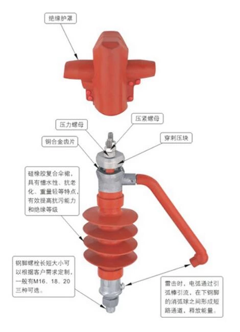
This device secures insulated conductors and protects overhead insulated conductors from lightning strikes. Suitable for copper and aluminum overhead insulated conductors.
Specifications
| Model Specifications | Wire Cross Section Range (mm²) |
| FEG-12/5 | 50-240 |
|
Performance Parameters
1. Lightning full-wave impulse withstand voltage (peak): 100kV 2. 1-minute power frequency withstand voltage (RMS): 50kV 3. Power frequency arc current (RMS): 12.5kA 4. Rated bending withstand load: 5kN 5. Minimum nominal creepage distance: 360mm 6. Unique waterproofing paste applied to the puncture site |
 |
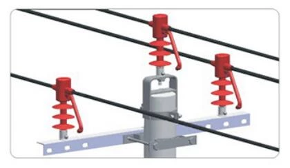
Installation diagram

|
Installation Instructions
Install this product's cable clamp on the crossarm, aligning the conductors parallel to the crossarm. Tighten the steel foot nut, similar to traditional insulator installation. Keep the arc striker pointed in one direction, toward the load side.
Piercing Clamping Methods:
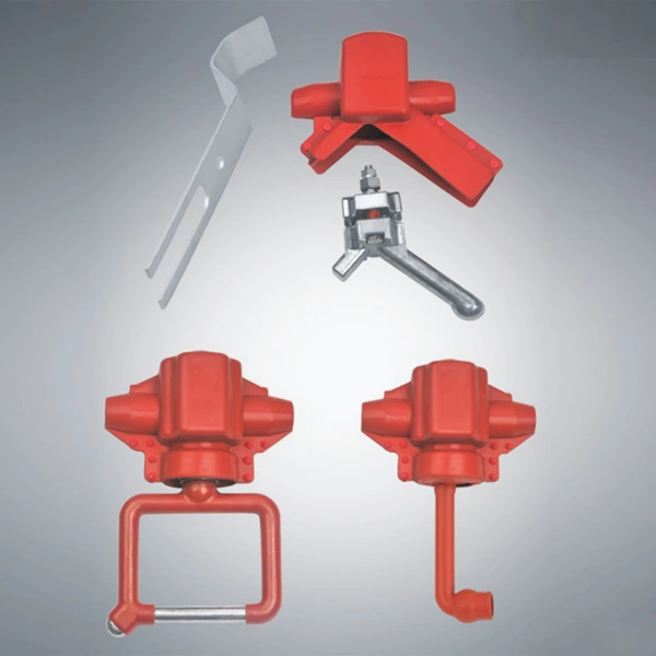
(I) Tightening Method with Alloy Aluminum Torque Nuts: Insert the insulated conductor parallel to the cable clamp. First, tighten the torque nut by hand. Then, use a socket wrench to tighten the nut alternately and evenly until the top of the nut falls off. Then, attach the insulating sheath to the cable clamp.
(II) Tightening Method with Standard Nuts: Set the torque wrench to a value of 20-35 NM based on the conductor cross-section and weather temperature. Use the torque wrench to tighten the two pressure nuts alternately and symmetrically. Tighten until the wrench reaches the set torque value. Then, tighten the backup nut to prevent the pressure nut from loosening. Finally, attach the insulating sheath to the cable clamp.
Non-piercing wire clamping method:
Strip the insulated wire to a length of approximately 65-80mm, wrap it with aluminum tape, and insert it into the insulator clamping hardware. Tighten the compression nut with a wrench to force the clamping block to compress the wire. Then, install the insulation sheath onto the clamping hardware.


