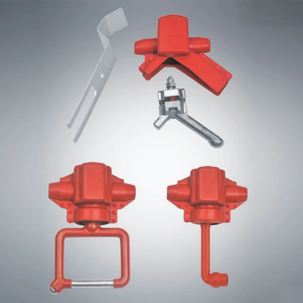
Multifunctional overhead insulated cable grounding wire clamp, used for the support from electric lightning burned in the insulator protective 1-10 kV overhead insulated cable. Can also be used to test the insulation cable grounding protection.voltage limiter for 10kV overhead insulated cable, when the lightning overvoltage occurs, lightning line clamp voltage between the ends do not exceed the specified value, the electrical equipment from lightning overvoltage damage; after the action, the system return to a normal state quickly.
Parameters and scope of application for lightning clamp 10kV overhead insulated cable
| Type & Spec. | Mm² Cable Cross-Sectional Area | Mm Conductor Diameter | Insulated Cable Diameter | Conditions of Usage | |
| Thin Type | Universal | ||||
| SL FH10-70/150 (SLFH10-1) | 50 70 95 120 | 8.3 10.0 11.6 13.0 | 13.8 15.0 16.6 18.0 | 15.1 16.8 18.4 19.8 | 1) The ambient temperature is not high +50°C, not lower than -40 °C 2) The elevation does not exceed 1000m 3) Power Frequency 50-60Hz 4) The maximum wind speed is not more than 35m/s. 5) The earthquake intensity below 8 degrees in the following areas |
| SLFH10-185/240 (SLFH10-2) | 150 185 240 | 14.6 16.2 18.4 | 19.6 21.2 23.4 | 21.4 22.6 24.8 | |
Designation & Classification
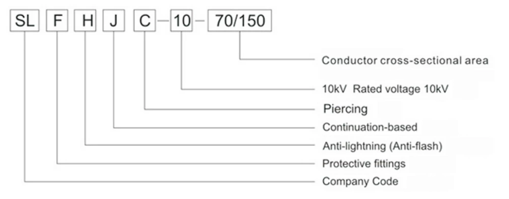
Model tab is marked by three groups of numbers or letters for 10kV overhead insulated cable lightning clamp. The meaning of the logo is:
Multifunctional Overhead Insulated Cable Lightning Arrester Clamp Structure Overview
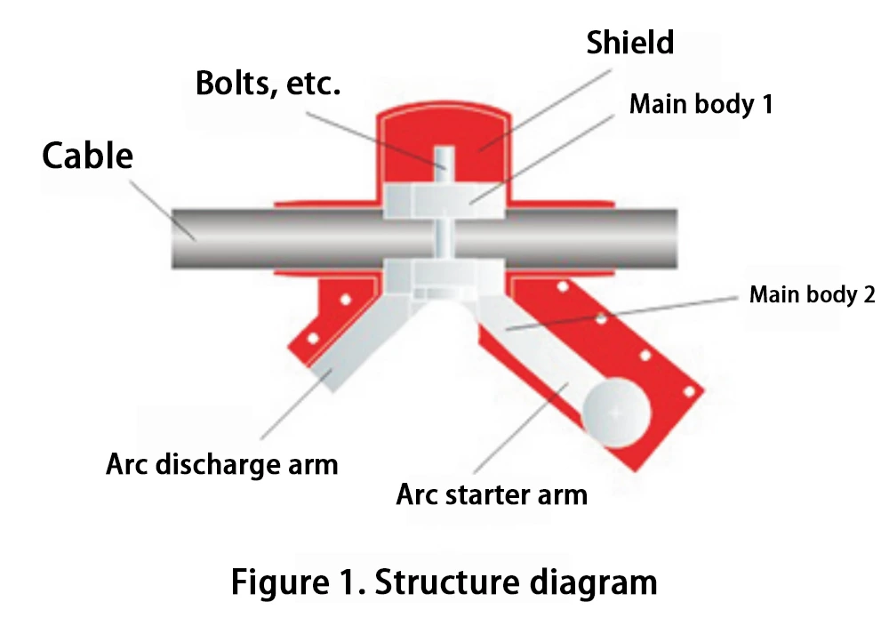
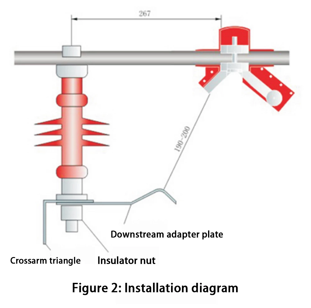
The multifunctional overhead insulated cable lightning arrester clamp consists of five parts: a protective cover, fastening bolts and constant torque nuts, body 1, body 2 (including arc discharge arm, grounding ring, and arc striker arm), and a downlink adapter plate (see Figure 2).
Working Principle of the Multifunctional Overhead Insulated Cable Lightning Arrester
1. Causes of Lightning Strike on Insulated Cables at the Insulator Support:
In a lightning field, due to the unique shape and installation location of utility poles, lightning overvoltage can cause induced discharges in the overhead insulated cables near the contact points with the insulator supports. The powerful instantaneous current can burn through the overhead insulated cables. During thunderstorms, this phenomenon of lightning strikes on overhead insulated cables is common.
2. Lightning Protection Principle of the Multifunctional Insulated Cable Lightning Arrester:
In a lightning field, when a multifunctional insulated cable lightning arrester is installed on an overhead insulated cable (see the installation diagram in Figure 2), once a critical overvoltage is generated, the arc discharge arm of the multifunctional insulated cable lightning arrester immediately discharges the induced lightning current to the ground through the downward connecting plate, thereby preventing the overhead insulated cable from being struck by lightning.
3. During non-thunderstorm conditions, the multifunctional insulated cable lightning arrester is connected to the ground wire via its grounding ring, providing grounding protection and temporary electrical testing.
Installation Method
1. Select a multi-functional insulated cable lightning arrester clamp appropriate for the cross-sectional area of the insulated cable.
2. It is recommended that the multi-functional insulated cable lightning arrester clamp be installed on the load side of the insulator. The location and dimensions are shown in Figure 2.
3. To protect the cables from lightning strikes, a multi-functional insulated cable lightning arrester clamp should be installed on each three-phase cable on each pole.
However, in most cases, the metal crossarm on the pole is mounted on two of the three insulators (see Figure 3). In this case, for a two-phase cable installed on a metal crossarm insulator, a multi-functional insulated cable lightning arrester clamp should only be installed on the load side of one of the two phases. On the next adjacent pole, the multi-functional insulated cable lightning arrester clamp installed on the metal crossarm insulator should be installed on the other phase of the cable (i.e., the two-phase cables on the metal crossarm insulator should be installed alternately on alternate poles). Only two multi-functional insulated cable lightning arresters are required for each three-phase cable on each pole.
Questions and Answers
1. When there are tall buildings near utility poles, is it necessary to install a multifunctional lightning arrester on the load side of the insulated cable supported by the insulator?
Answer: When a lightning strike develops into a short, rapid series of strikes, it is not a single, continuous breakdown nor a single, direct strike. It is common for lightning to leap over the top of a building and then strike below it laterally. Therefore, when there are tall buildings near utility poles, a multifunctional lightning arrester should be installed on the load side of the insulated cable supported by the insulator to ensure protection from lightning strikes.
2. Will dense fog cause a short circuit between the lightning arrester and the ground?
Answer: No. According to safety clearance regulations for outdoor power distribution, the clearance between live parts and the ground at 10kV should be greater than 200mm. The clearance between this lightning arrester and the ground is (190-200)mm + the distance h from the downstream support plate to the ground, where (190+200)+h>200mm. In dense fog, atmospheric overvoltage plays a dominant role. In normal weather, the atmospheric breakdown voltage is about 6kV/mm; in dense fog, the atmospheric breakdown voltage is only about 1kV/mm; at this time, the breakdown voltage from the lightning conductor clamp to the ground = 190*1kV+h*1kV is much greater than 19kV. Therefore, the 10kV voltage cannot be broken down. In other words, there can be no short circuit to the ground in foggy weather.
3. Why should the lightning conductor clamp be installed on the load side of the insulated cable supported by the insulator?
Answer: It is to prevent the induced lightning waves from spreading to the user.
4. Why is there only one lightning conductor clamp installed on the two-phase insulated cable supported by two insulators on the metal crossarm, instead of two?
Answer: As shown in Figure 3 (1), a lightning conductor clamp (red circle in the figure) is installed on the two-phase insulated cable supported by two insulators on the metal crossarm. In the lightning field, since the two lightning conductor clamps use the same metal crossarm, when the overvoltage in the lightning field is large enough, the two lightning conductor clamps may form a phase-to-phase short circuit through the downlink connecting plate and the metal crossarm. To avoid this possible short circuit, lightning arrester clamps cannot be installed simultaneously on two insulated cables supported by two insulators on a metal crossarm. The installation shown in Figure 3 (2) is correct. On the next adjacent electric pole, the lightning arrester clamp installation method should be reversed from Figure 3 (2), as shown in Figure 3 (3), and the lightning protection function will be foolproof. It can also ensure that each phase of the cable is grounded and temporarily tested for electricity in non-thunderstorm weather, achieving the purpose of using one clamp for multiple purposes. This relationship does not exist between insulators that are not connected by metal crossarms.


